Does the SWL screw jack need a protective cover?

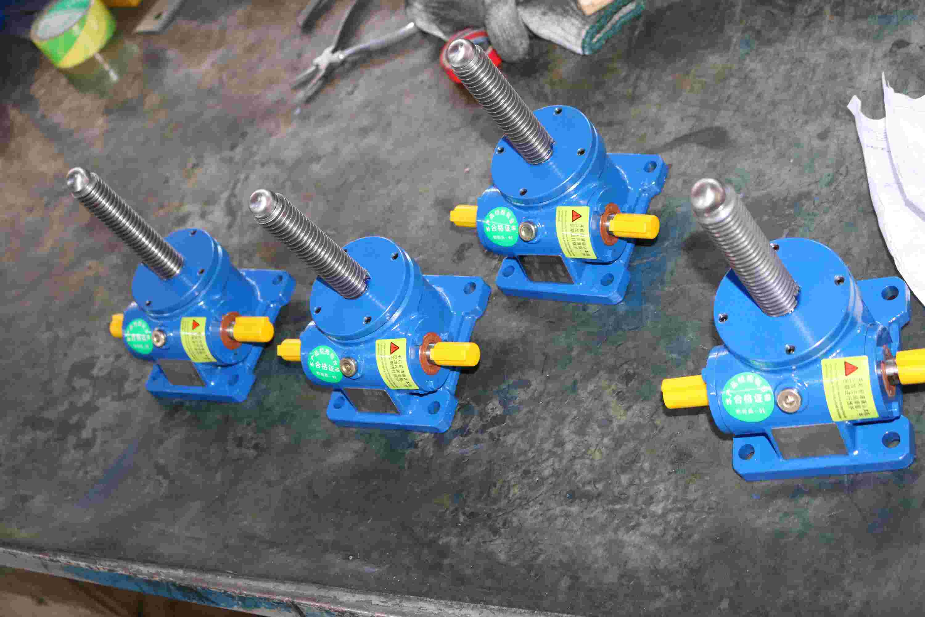
SWL screw jack can be optionally equipped with a protective cover. However, during actual selection, most customers did not choose a protective cover. It may be due to cost-saving reasons, or there may be no choice due to other reasons.
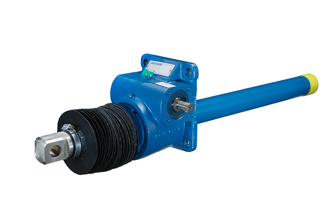
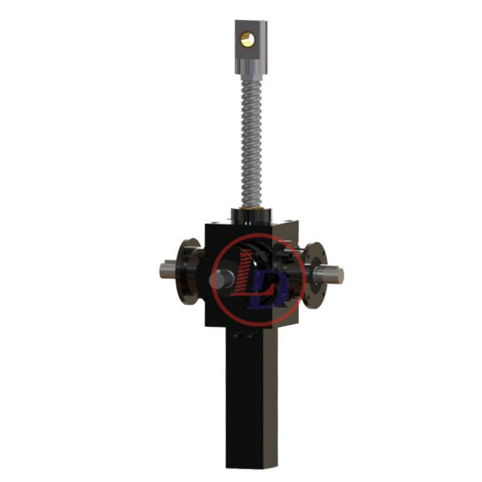
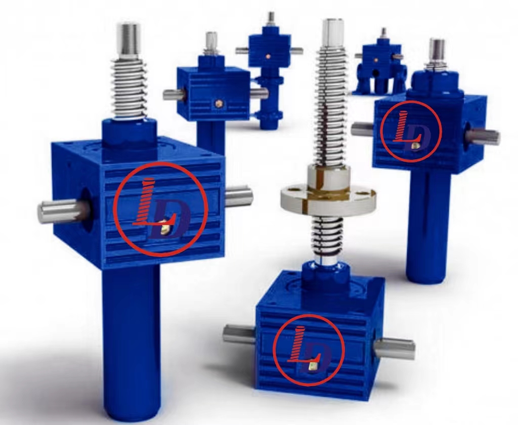
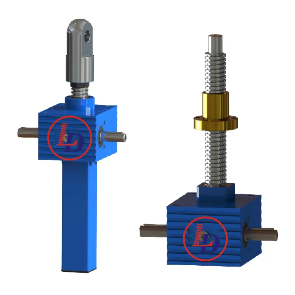
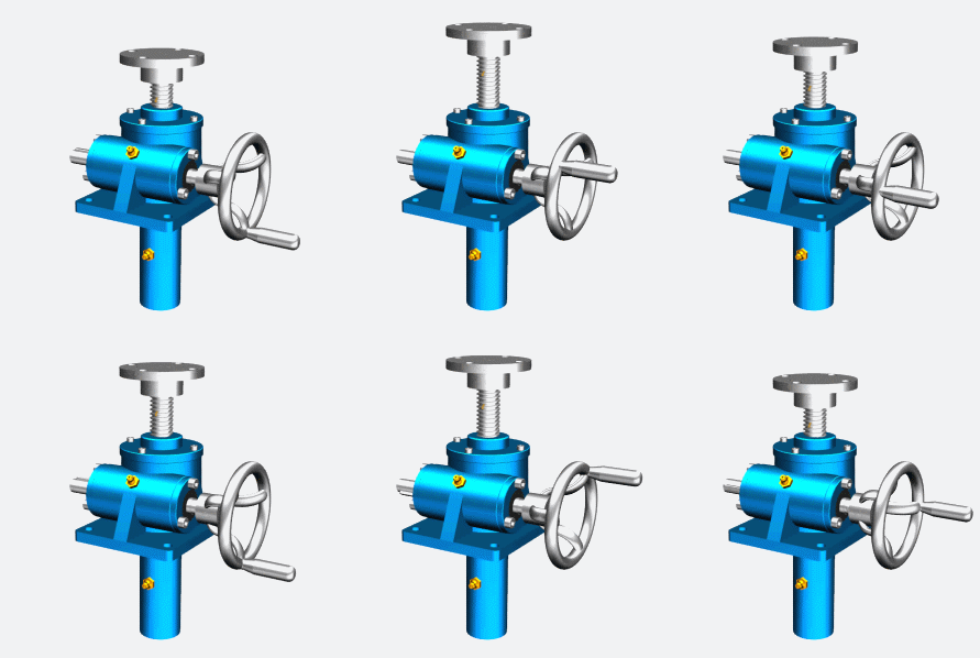
SWL screw jacks

Today Lude Transmission will take you to know about the protective cover, which is not only applicable to SWL screw jacks, but also to other types of screw jacks.


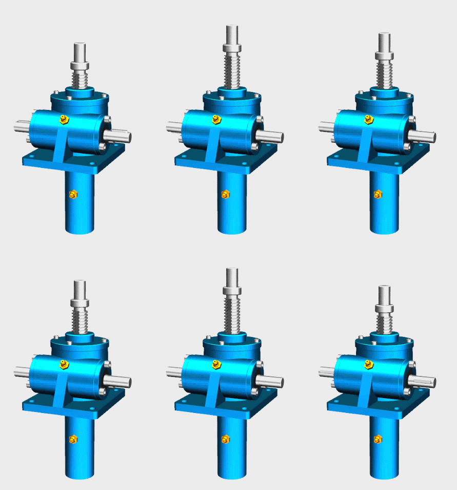
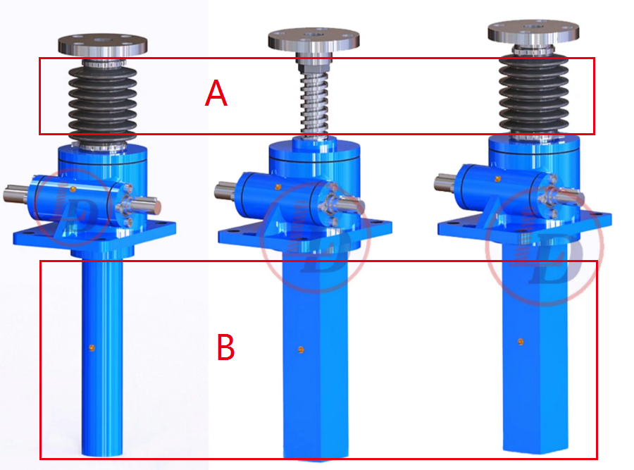
We divide the protective cover into two types, which are installed in the upper area A and the lower area B of the screw jack (see the picture below).
SWL screw jacks


The screw rod part that is constantly telescopic and moving uses a soft protective sleeve, also called a bellows boot. The bellow boot can expand and contract with the expansion and contraction of the screw rod, so that it is not easy to cause damage to the protective cover. Just install the protective pipe on the lower part as a protective cover. Divided into cylindrical type and square tube type.
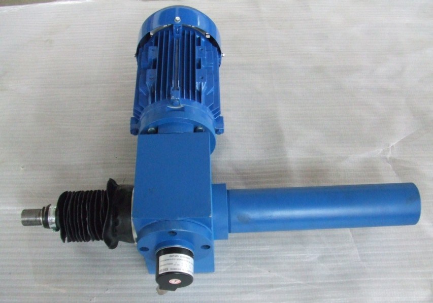
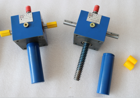
SWL screw jacks

SWL screw jacks

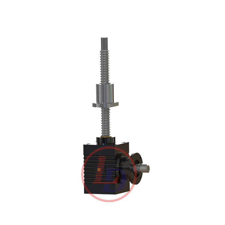
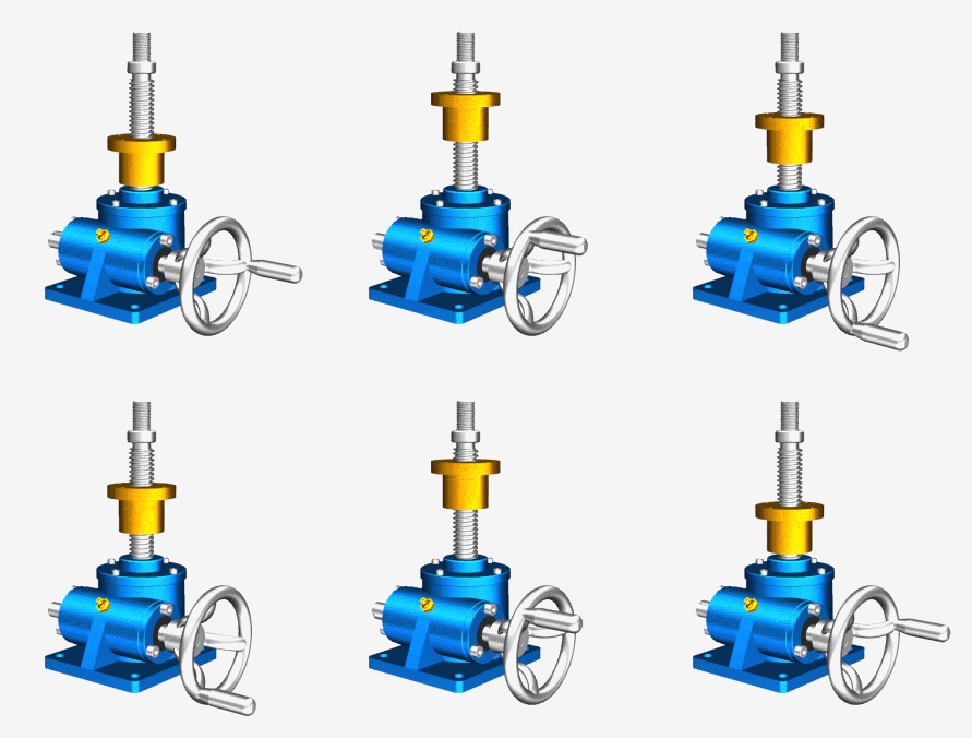
What if it is a nut movement screw jack? The nut movement can also be fitted with a dust cover. Just install a bellows above and below the nut.
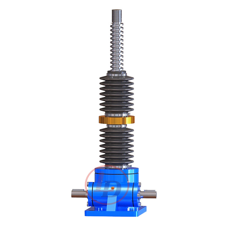
SWL screw jacks

The protective cover plays a very important role in protecting against dust, oil, corrosion, etc. If you have enough budget, it is still recommended to choose a protective tube and dust cover.
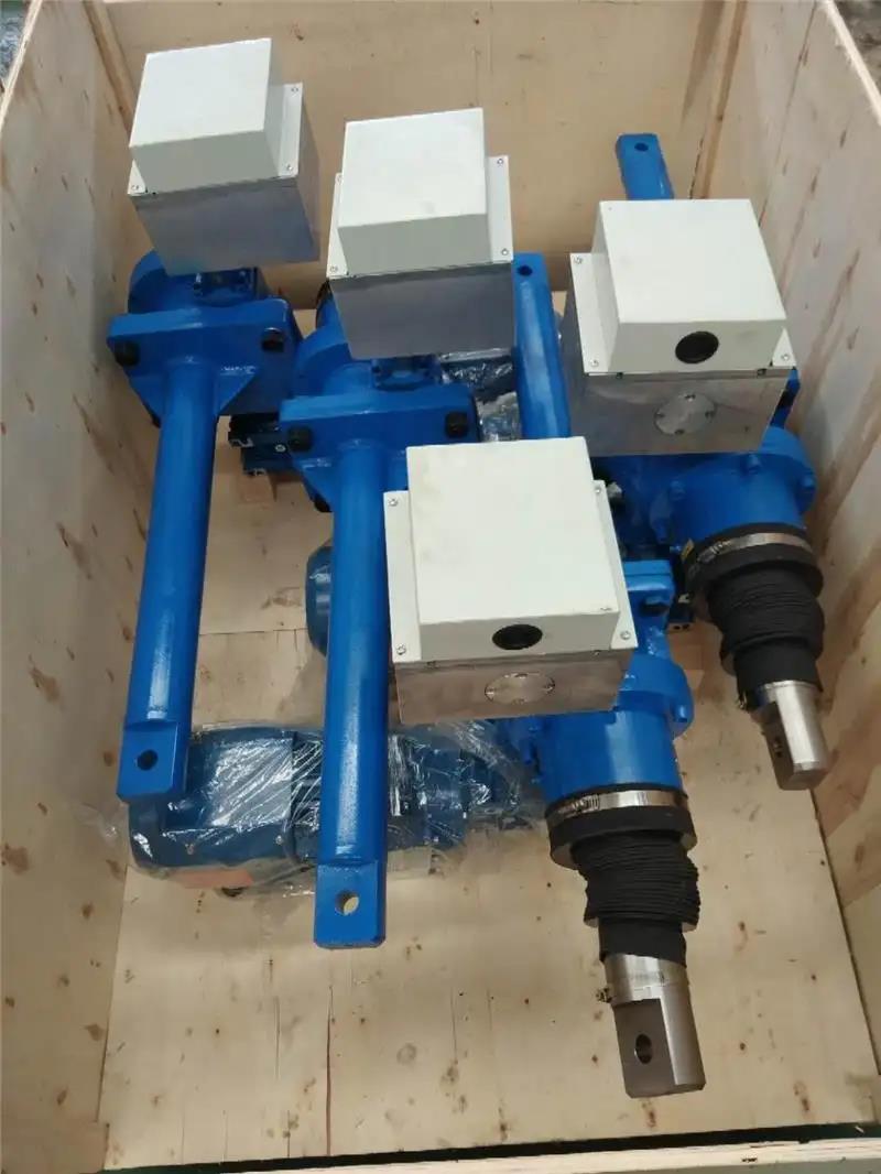
SWL screw jacks


If you need this product, please feel free to consult us.
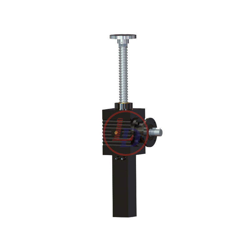


What are the characteristics of bevel gear jacks?

Bevel gear jacks use the same trapezoidal or acme screws used in machined screw jacks to move the load. However, bevel gear jacks use bevel gears inside the housing instead of worm gearing. Bevel gears are more efficient than worm gearing,and they have lower ratios that result in higher speeds and travel rates. Typically, bevel gear jacks maintain self-locking characteristics while providing higher travel speeds.


bevel gear screw jack

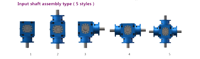
Another benefit of bevel gear jacks is their I/O shaft flexibility. They are available in single shaft, two shaft and three shaft configurations. In two and three shaft configurations the jack offers right angle characteristics with the ability to divide input power or torque, sending it equally in different directions. Flexibility in shaft configuration makes bevel gear jacks ideal for multiple jack configurations and can eliminate the need for stand-alone right angle gearboxes used in many worm gear jack systems.

bevel gear screw jack

Bevel gear jacks are well suited for light and moderate duty cycle applications and they are priced slightly above worm gear or machined screw jacks because of their greater efficiency, flexibility and speed characteristics. While a bit more expensive, bevel gear jacks reduce the number of required components in multiple jack systems, which helps balance the difference in price.

bevel gear screw jack


What are the two basic transmission types of screw jacks?

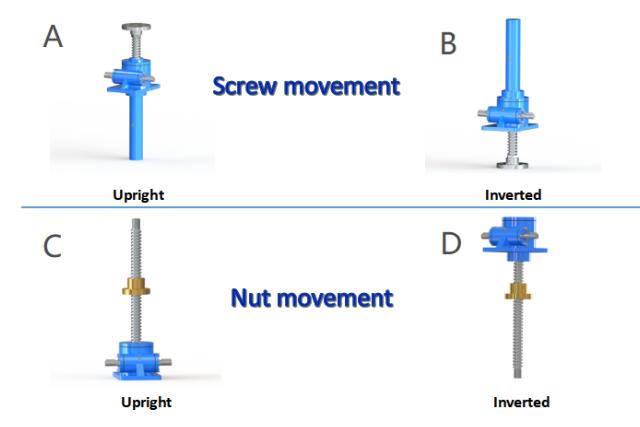
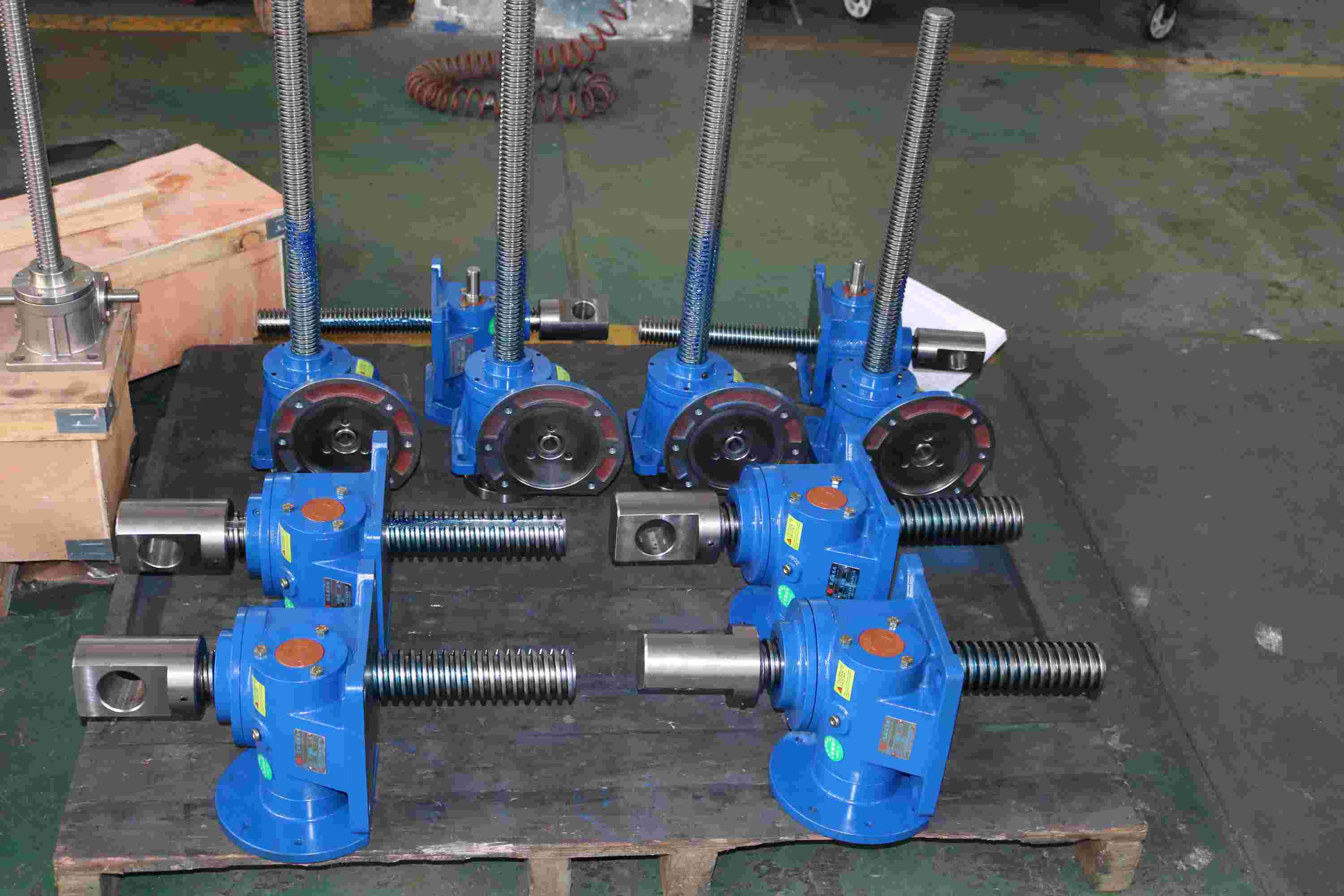
There are two types of basic transmission forms of screw jacks.

screw jacks

1.Nut Movement

In Brief: When the worm shaft is rotated the lead screw rotates in the body of the screw jack at the same rate as the worm gear. The nut on the lead screw moves in a linear direction along the screw when fixed to a structure that prevents it from rotating with the screw. This design is also available with a “Safety Nut”.

In Detail: When a screw jack unit is operated, the rotation of the worm shaft causes the worm gear to rotate. For rotating screw jacks the lead screw is fixed to the worm gear and they rotate at the same speed. As the worm gear turns, the friction forces on the screw thread act to turn the nut also. The greater the load on the screw jack unit, the greater the tendency of the nut to turn. It is obvious that if the nut turns with the screw, it will not raise the load. Therefore the nut needs to be fixed to a structure to prevent rotation.

screw jacks

2.Screw Movement

In Brief: The lead screw translates through the body of the screw jack when the lead screw is prevented from rotating with the worm gear. This is typically done by fixing the end of the lead screw to the structure that needs to be moved linearly.

In Detail: When a screw jack unit is operated, the rotation of the worm shaft causes the worm gear to rotate. For translating screw jacks the worm gear is threaded to accommodate the lead screw thread. As the worm gear turns, the friction forces on the screw thread act to turn the screw also. The greater the load on the screw jack unit, the greater the tendency of the screw to turn. It is obvious that if the screw turns with the nut (worm gear), it will not raise the load. In those cases where a single unit is used, and where the load cannot be restrained from turning, it is necessary to screw jack with an anti-rotation mechanism (keyed screw jack).

screw jacks


What should pay attention when using screw jacks ?

What should you pay attention to when using the screw jack? This is also crucial for us who often use jacks .It enables us to better understand the screw jacks, thus reducing unnecessary troubles during use.

The specific precautions for the screw jack are as follows:

Firstly, always keep the surface of the screw jack clean, regularly check whether the internal structure is intact, make the pinion in the rocker flexible and reliable, and lift the lifting sleeve freely.


Secondly, the friction surface between the lifting sleeve and the housing must be oiled at any time. Other oil filling holes should be lubricated regularly.


Thirdly, in order to take into account the safety in use, the jack should not be overloaded, work with illness, it is not appropriate to use more than one to avoid danger.


Fourthly, The screw jack must be checked regularly, depending on the level of use and the working environment. It is advisable to check if there is a lubricant leak in the housing. If this happens, you need to find and remove the cause and fill the lubricant with the correct level.The lubrication conditions of the threaded spindle must be checked regularly (if necessary, recovery must be made) and the presence of any foreign matter. Safety components must be inspected according to applicable specifications.


Which type of screw jack should you choose?

When facing with the need to lift, lower, push or pull a load,especially a heavy load and hold it in the correct position, as crew jack or multiple screw jack system may provide the best linear motion solution when considering its performance/cost ratio. There are 3 main types of screw jacks:machine/worm gear screw jacks,ball screw jacks, and bevel gear screw jacks. Within these, there are 3 subcategories related to the mode of operation: Translating, Keyed, and Rotating/Traveling nut.  Let's see how these three subcategories move in below ,


In order to know if a screw jack or screw jack system could be a solution for your application, you will need to consider which type of screw jack to select. There are worm gear screw jacks, bevel gear screw jacks and ball screw jacks, and each has several different options and configurations.


To determine the type of screw jack that is best for your application, you need to consider several factors, including: load, self-locking capabilities, travel rate or travel speed, efficiency, accuracy, duty cycle and price,etc.


Double Section Screw Jack

The double-section screw structure consists of two screws and two nuts. The diameter of the first-stage screw is larger than that of the second-stage screw. There is a keyway on the first-stage screw, and the inner hole of the worm gear is a through hole with a keyway. When the worm gear rotates counterclockwise, the key structure drives the first-stage screw to rotate. A nut with an internal thread is installed above the turbine and fixed on the top of the box. It cooperates with the thread of the first-stage screw. The screw and the nut produce relative movement, and the screw rises or falls. The second-stage structure is also a combination of a pair of nuts and screws. The secondary nut is connected to the primary screw and rotates and rises and falls with the primary screw. The secondary screw is connected to the user’s equipment. The screw does not rotate, but only rises and falls.

  1. The primary and secondary screws have the same axis;
  2. Compact structure, small size, saving space and cost;
  3. Reduce the weight of the overall platform, reduce the output power of the drive source, energy saving and environmental protection;
  4. Double the speed. Compared with a single-section screw, the speed is twice that of a single-section screw at the same input speed;


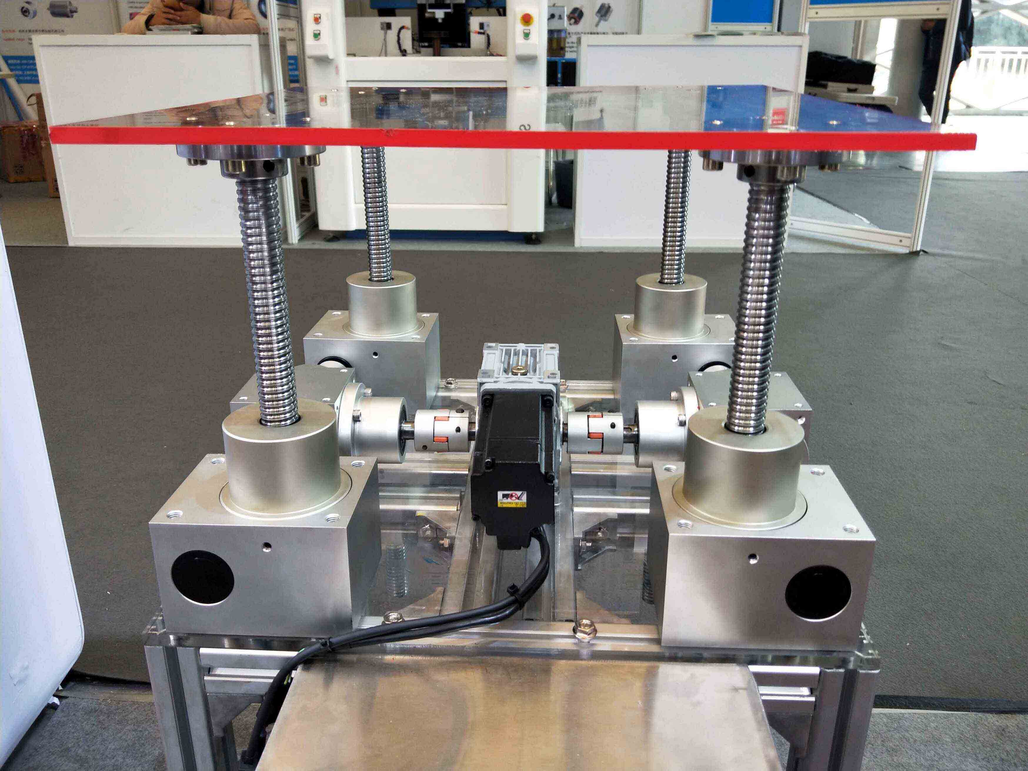
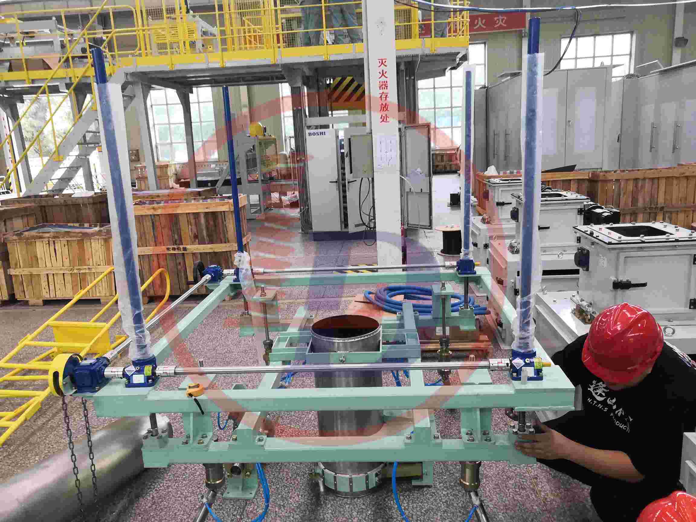
How to avoid excessive deviation when installing multiple screw jack system?

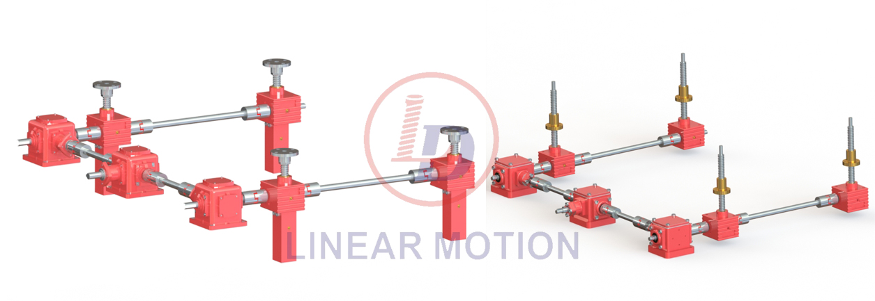
The screw jack system is widely used in situations with long spans and excessive loads. The use of screw jacks typically involves a multi-unit synchronized configuration. This approach ensures that the load on each individual screw jack does not exceed its capacity, guaranteed sychronized movement of all units to prevent lateral forces, and ehances overall stability and safety of the solution.

The desigan phase for a synchronized screw jack system is crucial,requiring customers to provide relvent data and considering installation space, operating conditions, limit switches, and other aspects. However, after completion and production delivery, on-sit installation at the customer's premises is equally important. We need to pay attention to various issues such as center height alignment,coaxiality, guide devices,and gearbox orientation determination.


Today we want to discuss how to avoid excessive deviations during the multi-unit screw jack system.First, let's start with the perparation steps: After receiving the screw jacks from the customer, it's necessary to ensure that the output and input shafts of units like gearbox and motors are at the same horizontal level. If there is a difference in center height, you can chosse to add appropriate thickness washers to make them consistent. When connecting with couplings or connection rods, it's necessary to calibrate coaxiality to prevent tilting or binding situations.

If a lifting platform is required, attention must be paid to its installation. We need to ensure that the mountibng surface of the screw or nut is at the same horizontal heigth, and the mounting surface of the screw jack should also remain level.Additionally, adjust the mounting holes of the screw head(or nut mounting holes)so that they align with the mounting holes of the support platform before installation installing it. It's important to note that during installation,lateral forces should not be applied to the screw. Lastly, to avoid excessive deviation when multiple screw jack system are installed, we must confirm that there are no errors in the dimensional deviations of each axis before connecting the equipment.Before assembling the screw jack with the driven source and other devices., check for dimensional deviations in shaft diameters,keys, and keyways to prevent damage to bearings from over-tightening or affect power transmission from under-tightening.After installation, lubricate all necessary parts and conduct test runs.If any issues arise during testing, immediately stop operation and only restart once everything is confirmed to be normal.

How to check the stability of the lifting spindle of the screw jack and the linear actuator


Screw stability verification: known load 100KN, stroke 500mm, speed 60mm/min, no guide rail, usage coefficient 1.5, low operating frequency, calculated model For (Heavy Duty Electric Linear Actuator model SCA200-V1-500-FL-P2):

lifting Screw specification Tr80*12

1. Known conditions

Load F=100KN=100,000N

Stroke S=500mm

Speed v=60mm/min

Usage coefficient K=1.5

Screw specification Tr80*12 (diameter 80mm, pitch 12mm)

2. Analysis of screw force

The screw mainly bears the axial load, so we need to calculate the stress of the screw under the axial load.

• Screw diameter d=80mm=0.08m

•Screw cross-sectional area A=π (2d)2= π(20.08)2=0.005027㎡

•Axial load Fax=K*F=1.5×100,00N=150,000N

3. Calculation of screw stress

Screw stress o =AFax=0.00502715000=2983866.67Pa

4. Check the stability of the screw

For the stability of the screw, we mainly pay attention to whether it will flex. Since the screw is usually installed on the fixed bracket and its length is relatively short (500mm), the possibility of buckling is relatively small. However, in order to evaluate more accurately, we can use Euler's formula to estimate the critical bending load of the screw.

1. Screw length=500mm=0.5m

2. The elastic modulus of the screw material E (set to steel, E≈210GPa=210×109Pa)

3. Screw moment of inertia I=π 64d4= π64×(0.08)4=2.01062×10⁻⁷m4

Eular critical load Fcr can be calculated by the following formula:

Fcr=12 π2EI=(0.5)2π 2×210×109×2.01062×10-7=2,649,444.44N

Because Fax=150,000N<Fcr=2,649, 444.44N, the screw is stable under axial load.

5. Summary
After calculation, it is confirmed that the screw (specification is Tr80*12) equipped with the linear actuator model SCA200-V1-500-FL-P2 is at a load of 100KN, stroke of 500mm, speed of 60mm/min, and a coefficient of use of 1.5 And the linear actuator is stable under the condition of low working frequency.

introduction of screw jack's ratio

The transmission ratio of a worm gear screw lift (often just called a worm gear) refers to the ratio between the number of turns the worm (the driving gear) makes for one complete revolution of the worm wheel (the driven gear). This ratio dictates how much mechanical advantage is gained through the system, and also influences the speed reduction and torque increase.

Factors Related to the Transmission Ratio:

  1. Lead of the Worm:

    • The lead is the distance the nut (or worm wheel) moves along its axis per one complete revolution of the worm. It plays a direct role in the transmission ratio.
    • A higher lead results in a faster movement of the worm wheel, but with a higher mechanical advantage (lower ratio) as the gear ratio is influenced by how far the worm travels per turn.
  2. Number of Teeth on the Worm Wheel:

    • The number of teeth on the worm wheel relative to the number of threads on the worm also affects the ratio.
    • In general, the more teeth on the worm wheel relative to the worm, the lower the transmission ratio.
  3. Number of Threads on the Worm:

    • Worms can have one or more threads (called single-start or multi-start worms).
    • A multi-start worm will reduce the transmission ratio, as each turn of the worm moves the worm wheel by a larger distance.
  4. Pitch of the Worm:

    • The pitch (distance between adjacent threads) also influences the ratio. A finer pitch (smaller thread spacing) typically results in a higher transmission ratio.
  5. Friction and Efficiency:

    • Worm gears have a high frictional contact between the worm and the worm wheel, which can influence the effective transmission ratio, especially at higher loads.
    • Efficiency is typically lower in worm gears compared to other types of gears, which can cause some discrepancy between the theoretical and actual ratio.

How to Calculate the Transmission Ratio:

The transmission ratio can be calculated using the following formula:

Transmission Ratio=Number of Teeth on the Worm WheelNumber of Threads on the Worm=ZwZs\text{Transmission Ratio} = \frac{\text{Number of Teeth on the Worm Wheel}}{\text{Number of Threads on the Worm}} = \frac{Z_w}{Z_s}

Where:

  • ZwZ_w = Number of teeth on the worm wheel.
  • ZsZ_s = Number of starts (threads) on the worm.

Example:

If the worm wheel has 40 teeth and the worm has a 2-start thread, the transmission ratio would be:

Transmission Ratio=402=20\text{Transmission Ratio} = \frac{40}{2} = 20

This means for each full rotation of the worm, the worm wheel will turn 1/20th of a rotation.

Additional Considerations:

  • Self-locking feature: Worm gears often have a self-locking property, where the worm can drive the worm wheel but the worm wheel cannot drive the worm. This property comes into play in applications like screw lifts where load holding is important.

Reasons for using electric actuators in photovoltaic power generation

electric linear actuators


Regardless of whether it is a standard electric linear actuator, a small-sized actuator, or even a micro actuator, these devices have seen strong development and application across various industries. One common aspect of their use is their significant role in the renewable energy sector. Here, we will focus on the development of electric actuators in the field of photovoltaic (PV) power generation.

1. Reasons for Applying Electric Actuators in the Photovoltaic Industry
The idea of using electric linear actuators in PV systems emerged due to the high cost of solar panels, which greatly limited the widespread adoption of such products. Under these circumstances, there was a strong need for alternative products, leading to further development of electric electric linear actuators.

2. Development of Electric Actuators in the PV Industry
From the early stages of technology to the present day, photovoltaic power generation has evolved from expensive solar cells to more cost-effective polycrystalline silicon cells, with a significant expansion in application fields. During this process, the use of components has also changed. In the past, fixed brackets were mostly used in power generation systems. However, the current trend has shifted toward actuator-based tracking systems.

3. Recognition of Electric Actuators in the PV Industry
Due to the high efficiency and stability of actuator-based tracking systems, they have received widespread recognition from both the government and industry peers. This has further encouraged investment in this area, ushering in a promising period of development for electric linear actuator tracking systems.

4. Categories of Electric Actuator-Based PV Tracking Systems
This power generation model can be broadly classified into two main types: single-axis linked tracking systems and dual-axis tracking systems. Regardless of the type, electric linear actuators serve as the driving force for these tracking systems. Because of this, strict requirements are placed on their service life—they must match the lifespan of the solar panels in order to maximize the overall efficiency of the PV power generation system.

Electric Actuator-Based PV Tracking Systems